 |
| Energy Storage System (ESS) |
Methods of generating electricity by renewable energy such as wind power and solar power, rather than the methods by conventional power plants are becoming important both politically and technically not only in Korea but also around the world. In the case of Korea, the importance of renewable energy is emphasized as the country pushes for the "2050 carbon neutrality" policy. However, there are certainly drawbacks to renewable energy. Wind power and solar power are the representative sources of renewable energy. Wind power generators are affected by wind speed, and photovoltaic generators by solar radiation. Because of this inherent nature of renewable energy, the amount of power output from renewable energy is highly volatile. Many studies to reduce this volatility are going on , and in this post, we will first learn about ESS and how it is typically utilized to decrease bad natures of renewable energy and eventually to help stabilize power grid.
1. ESS Type
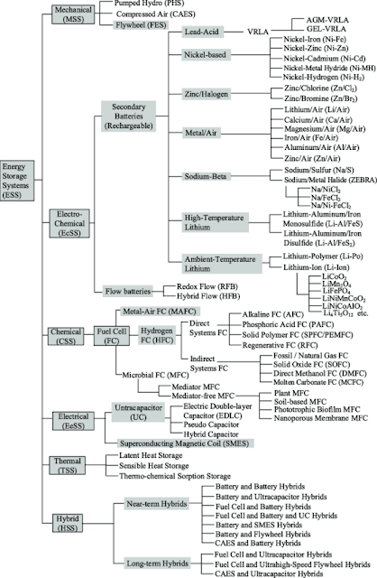 |
| ( Source: Paper 'Review of energy storage systems for electric vehicle applications: Issues and challenges) Types of ESS |
 |
| ( Source: Soo Kyung Chemical Co.. Ltd ) Charging discharge of lithium-ion batteries |
2. Utilize ESS in the power system
As shown in the figure below, when ESS is utilized within the power system, it consists of energy storage devices (ES), power conversion system (PCS), and related power management system (PMS). Energy storage devices must be charging a certain amount to charge and discharge for a certain period of time. PMS is intended for charging and discharging control via ES and PCS, and is equipped with monitoring and control algorithms. ESS in these configurations can be used for significant power quality(power factor) improvements, frequency regulation, and load transfer purposes.
 |
| ESS components and concepts |
2-1. Power Quality
In bus voltage and load current, voltage and current distortions such as harmonic and instantaneous voltage drops occur, which adversely affect power quality. Power quality is very important in cases such as semiconductor processes that require normal factory operation with good power quality. As a countermeasure, flywheels or battery-based ESSs with fast reactivity are used, and battery-based ESSs have long discharge times, making them suitable for using ESSs for improving power quality.
2-2. Frequency Adjustment
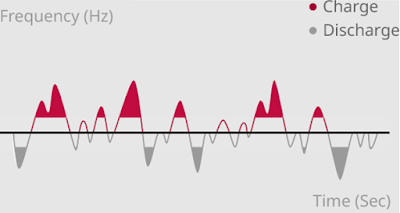 |
| ESS charging, discharging according to frequency adjustment |
2-3. Load Shifting
As mentioned earlier, renewable energy is characterized by high volatility. In power systems, this nature must be suppressed or predicted to balance generation and demand. Otherwise, even if renewable energy generators are prepared for the connection to the power system by meeting the grid code, there will be restrictions on the connection. The ESS can shift the energy generated from renewable power sources from low demand area to high demand area, which is called load shifting.
In order to see the effect of shifting the load, the capacity of the ESS must be determined by considering output and its volatility of the renewable power plant or the size of the peak demand. Also, charging and discharge time in batteries must be long, ranging from minutes to hours. Suitable storage devices include CAES, pumped water power generation, and batteries.
 |
| ( Source: Paper 'PEAK SHAVING CONTROL METHOD FOR ENERGY STORAGE' ) ESS charging, discharging following load shifting |
|
| Energy Storage System (ESS) |
1. ESS 종류
|
| ( 출처 : 논문 'Review of energy storage systems for electric vehicle applications: Issues and challenges) ESS의 종류 |
|
| ( 출처 : Soo Kyung Chemical Co.. Ltd ) 리튬이온전지의 충방전 |
2. 전력 계통 내 ESS 활용
|
| ESS 구성 요소와 개념 |
2-1. 전력 품질
모선전압과 부하전류에서 고조파, 순간적인 전압강하와 같은 전압, 전류의 왜곡 현상이 발생하는데, 이는 전력 품질에 악영향을 준다. 좋은 품질의 전력을 공급받아 정상적인 공장 가동이 이뤄저야 하는 반도체 공정과 같은 경우에 전력 품질은 매우 중요하다. 이에 대한 대책으로 빠른 응동성을 가지는 플라이휠이나 배터리 계열 ESS가 사용되고, 배터리 계열 ESS는 장시간의 방전시간을 가져 전력 품질 향상 목적으로의 ESS 사용에 적합하다.
2-2. 주파수 조정
|
| 주파수 조정에 따른 ESS 충, 방전 |
2-3. 부하 이전
앞서 말한 대로 신재생에너지는 변동성이 큰 특징이 있다. 전력 계통에서는 이 변동성을 억제하거나 예측하여 발전과 수요의 균형을 맞춰야 한다. 그렇지 못할 경우에는 계통과의 연결이 준비된 신재생 에너지원이더라도 연계에 있어서 제약이 발생하게 된다. 신재생 발전원에서 발생하는 에너지를 전력수요가 낮은 시간에서 높은 시간으로 옮기는 것은 ESS에 의해서 수행될 수 있는데, 이를 부하이전이라 한다.
부하이전의 효과를 보기 위해서는 신재생 발전설비 용량이나 피크수요 크기를 고려하여 ESS의 설비 용량을 결정해야 하며, 충, 방전시간도 수분에서 수 시간 정도의 긴 시간이어야 한다. 이에 적합한 저장 장치로는 CAES, 양수발전, 배터리 등이 존재한다.
|
| ( 출처 : 논문 'PEAK SHAVING CONTROL METHOD FOR ENERGY STORAGE' ) 부하 이전에 따른 ESS 충, 방전 |
댓글
댓글 쓰기