기본 콘텐츠로 건너뛰기

DC-DC Converter : Buck, Boost and Buck-Boost converter

 A voltage converter is an electric power converter that changes the voltage of an electrical power source. On this page, I am going to talk about the DC-DC converter. In the DC-DC converter, there are 3 types.

1. Step-down(Buck) converter: Where the output voltage of the converter is lower than the input voltage.

In a buck converter, there are two types of modes. Continuous conduction mode(CCM) and Discontinuous conduction mode(DCM). During CCM(Mode 1), while switch S is on, the voltage of the load is conducted as V_s. During DCM(Mode 2), while switch S is off, any current doesn't flow.
 V_a=F(t_on, f_s) is a linear function. t_on is the on pulse width. Controlling t_on is known as PWM control. f_s is the switching frequency.

 Low current ripple(by adding inductor)

This is a buck converter which provides a low current ripple by adding an inductor on load.

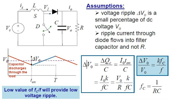
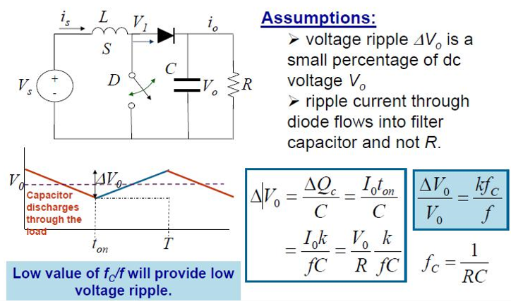
 Low voltage ripple(by adding capacitor)

This is a buck converter which provides low voltage ripple by adding inductor and capacitor on load

2. Step-up(Boost) converter: Where the output voltage of the converter is higher than the input voltage.

In Boost converter, there are two types of modes. Continuous conduction mode(CCM) and Discontinuous conduction mode(DCM). During CCM(Mode 1), while switch S is on, the voltage of the load is conducted as V_s by capacitor containing the charge. During DCM(Mode 2), while switch S is off, the inductor releases voltage in this mode.


Low Current Ripple

 Low Voltage Ripple


3. Step-down/step-up (Buck-Boost) converter: It can be used in any case.


Comparison of voltage ratio

This graph indicates voltage ratio by duty ratio in each converter. Notice that only the buck converter shows a linear relationship between the control (duty ratio) and output voltage. The buck-boost can reduce or increase the voltage ratio with unit gain for a duty ratio of 50%.

댓글

이 블로그의 인기 게시물

NPC Inverter and Psim Simulation

1. 3-Level NPC Type Inverter Fig 1. 3-Level NPC Type Inverter Fig 2, Switching  Fig 1 is 3-Level NPC Type Inverter and Fig 2 indicates how it works.  Fig 2 indicates how each switch is activated. There are 3 switching states which are called P, O, N. In each state, the output voltage becomes +V_dc/2, 0, -V_dc/2. Fig 3. Switching Mode  Left in Fig 3 indicates circuits when positive voltage and the right one is for negative voltage. Let's check how it works! Considering P switching state in positive voltage, S1 and S2 are on, and S3 and S4 are off. So we can ignore the circuit below. As a result, the output voltage is +V_dc/2. In the same way, you can see how the rest works. 2. Control Fig 4, SPWM  In Fig 4, we can see how SPWM works. The offset voltage is applied to control the circuit. The common value for offset voltage is 0. It makes the reference polarity voltage and the reference phase voltage same. 3. Circuit Fig 5. Circuit for Psim Simulation 1

Induction Motor : Stator, Rotor and Its Principle

0. Induction Motor   The induction motor is invented by the scientist Nikola Tesla and it is the most common motor type even today (Around 90%). About 50% of global electric power consumption is due to induction motors. The induction motor has basically two main parts: Stator and Rotor. 1) Stator: Stationary Part The stator is the stationary part of an induction motor like Fig 1-2. It is made up of various stampings with slots to carry 3 phase windings. The windings are geometrically divided 120 degrees separated. It does not require DC current to run the machine. 1. Induction Motor 2) Rotor: Rotating Part 2. :Various Rotors   The rotor is the rotating part of the induction motor. The rotor is simply a collection of conducting bars short-circuited by end rings. Its rotation is because of the interaction between the windings and magnetic fields producing a torque around the rotor's axis. There are many kinds of rotors: Squirrel-cage rotor, Wou

Voltage Source Inverter

Voltage Source Inverter  Voltage source Inverter is a device that converts power from a DC constant voltage source into AC form by switching behavior. The output voltage has a switching waveform and the output current has AC form. It is classified into two inverters: square wave inverter and PWM inverter. Fig 2. Voltage Source Inverter 2 Fig 1. Voltage Source Inverter 1 It consists of 3 pairs of 2 switching components. Depending on the switching condition, input and output voltage are determined. In order to prevent short circuit accident, switching component works in a commensurate way. 1. 3 Phase 2-Level Inverter Fig 3. General Circuit of 3 phase 2-level inverter Fig 3 is a common circuit of an 3 phase 2-level inverter. Line voltage has 3 level form which is +Vdc, 0, and -Vdc, The detail about this inverter is explained in one of my past posts titled as "Inverter: Single Phase Inverter and 3 Phase Inverter"  2. 3 Phase 3-Level Invert